Rpi Camv3 Oqt Connector
By Robert Russell
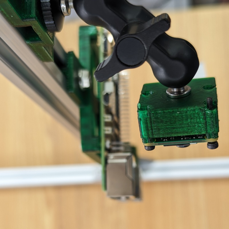
- 3 minutes read - 503 wordsHere’s another camera mounting block to 3d print. This part is meant to go with my previous design for mounting a Raspberry Pi on a t-slot rig. It’s just the minimum bit of plastic needed to join the camera module v3 to a 1/4-20" nut. Then the nut can be used to attach the camera module to a ball head like this one from Small Rig. Just like the rest of Gamma Camera the idea is to use 3d printed parts to bridge between common COTS parts.
Design
I designed this one in OpenSCAD with BOSL2 as well. The dimensions for the camera module are in the Raspberry Pi Camera Module 3 Product Brief. I think the v2 would also fit but I haven’t tested.
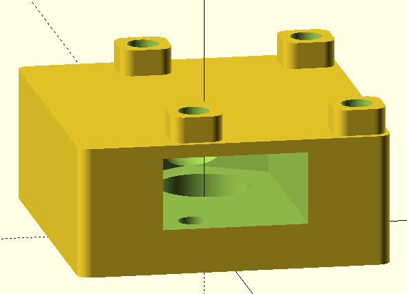
The part is a simple block with four M2 screw holes through it on one side and a nut trap in the center. The nut trap allows for easy attachment of the part to standard camera rig hardware using a 1/4-20" nut. The nut trap also introduces a challenging overhang in the 3d print though. Lately I’ve been printing supports in PLA and parts in PETG which has some great advantages for the finish on the final part but it needs a little attention to the slicer settings. It took a couple tries but eventually I had some good luck with the new organic supports along with “interface pattern spacing” set to zero.
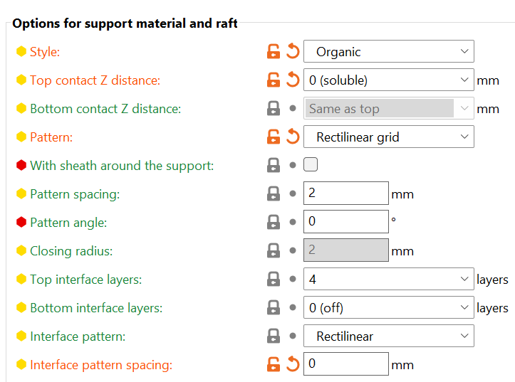
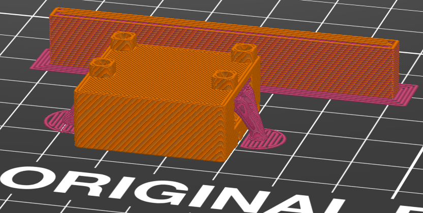
Setting the interface pattern spacing to 0 and the top contact Z distance to zero seems to create a flat surface upon which the PETG can be printed. On this design the organic supports sort of climb into the opening to create a surface for the overhang. The organic supports have a large contact area on the print bed so they stay anchored. Unfortunately they also climb up through a hole in the middle which makes them harder to remove. Maybe a support blocker there would be wise.
It’s a good first draft. I should have left a little space by the FPC connector but now that I have something working I want to get the parts assembled and move on to installing some software.
Here’s the OpenSCAD code, you should try printing some for yourself
include <BOSL2/std.scad>
include <BOSL2/screws.scad>

module draw_part() {
    diff() {
        cuboid([26, 24, 10], rounding=1, edges=["Z"], anchor=BOT) {
          position(TOP) back(3.5) xcopies(l=21, n=2) ycopies(l=12.5, n=2)
            cuboid([4, 4, 2], rounding=1, edges=["Z"], anchor=BOT)
              tag("remove") position(TOP) screw_hole("M2", length=12, anchor=TOP)
                position(BOT) nut_trap_inline(2);
          tag("remove") position(TOP) down(1) screw_hole("1/4-20", length=20, anchor=TOP)
            position(TOP) nut_trap_side(15, poke_len=20, anchor=TOP);
        }
    }
}

draw_part();
And the part that holds the ball head on the T-slot is in this post.
One challenge I’m still working on - the wipe tower that Prusa slicer makes for multimaterial isn’t great. It’s really stringy and made the print fail once. The PETG layer doesn’t seem to stick to the PLA layer. I don’t know if there are any more settings I can tweak but maybe building a couple blocks in each material near the wipe tower could help.