T-Slot bracket for a Raspberry Pi
By Robert Russell
- 4 minutes read - 844 wordsMy t-slot obsession has not let up. Last night I made a nice little design to easily secure a Raspberry Pi to a piece of 2020-profile extruded aluminum. This follows on from the 1/4"-20 to t-slot mount that I made recently. Just like that component, I used BOSL2 in OpenSCAD to quickly put it all together.
Design
Here’s the design for the part if you want to have a look.
include <BOSL2/std.scad>
include <BOSL2/screws.scad>

module pcb_tray() {
    diff() {
      cuboid([57, 66, 3], rounding=1.5, edges=["Z"], anchor=BOT) {
        tag("remove") xflip_copy(offset=12) yflip_copy(offset=15)
          position(BOT) cuboid([18, 21, 8], rounding=1.5, edges=["Z"], anchor=BOT);
        position(TOP) rect_tube(size=[57, 66], rounding=1.5, irounding=1.5, wall=7.5, h=3, anchor=BOT)
          xflip_copy(offset=24.5) yflip_copy(offset=29)
            cuboid([8, 8, 5], rounding=1.5, edges=["Z"], anchor=BOT)
              tag("remove") position(TOP) screw_hole("M2.5", length=8, anchor=TOP)
                position(BOT) nut_trap_inline(2, anchor=TOP);
      }
    }
}

module tslot_connection() {
  diff() {
    xcopies(l=75, n=2)
      cuboid([30, 20, 3], rounding=1.5, edges=["Z"], anchor=BOT) {
        // Bit that fits inside the T-slot.
        position(BOT) cuboid([30, 6, 4], rounding=1.5, edges=["Z"], anchor=TOP);
        // Shoulders with holes for the T-nuts.
        tag("remove") position(TOP) screw_hole("M5", length=3, anchor=TOP)
          // Cutout for the head of the T-nut.
          position(BOT) cube([6, 6, 4], anchor=TOP);
      }
  }
}

module draw_part() {
  tslot_connection();
  pcb_tray();
}

// Called in fit-test.scad and printable.scad.
// #draw_part();
While I was working on this I had a clever idea that mimics the way software is built. I called that file part.scad and created another file called fit-test.scad. Here’s what’s in that file:
$fn = 10;

include <BOSL2/std.scad>
include <BOSL2/screws.scad>

include <NopSCADlib/core.scad>
include <NopSCADlib/vitamins/extrusions.scad>
include <NopSCADlib/vitamins/pcbs.scad>

include <./part.scad>

color([0.2,0.2,0.4,0.3]) {
    down(10) left(50) yrot(90)
        extrusion(E2020, 100, false, cornerHole = false);
}

color([0.8,0.2,0.4,0.3]) {
    up(9.5) back(10) zrot(90)
        pcb(RPI4);
}

draw_part();

The fit-test file includes part.scad and calls the main method draw_part(). However it also uses NopSCADlib to draw a 2020 profile aluminum extrusion and a Raspberry Pi 4 PCB around the part. I actually edit part.scad in an external text editor and view fit-test.scad to check the details. Every time I save part.scad in the external editor, the OpenSCAD window showing the fit test automatically refreshes.
It’s a simple design with two holes to attach t-nuts with an M5 bolt or the hammerhead style bolt. I printed in PETG with PLA supports on the Prusa XL in under an hour. There are recesses for M2.5 bolts. Since these are close to the corners I find it convenient to squeeze the nut in with a pair of channel lock pliers. I noticed that there was some curling at the corners. Even though the PETG part that curled was resting on PLA and not the print bed. So I decided to print the last one upside down. I also added a little sprue on each corner to keep it from lifting off the bed. The sprue technique is inspired by this video from Slant 3D.
The sprues aren’t in either any of the source files above. I have a third file called printable.scad. Here’s what’s in it:
$fn = 100;

include <BOSL2/std.scad>
include <BOSL2/screws.scad>

include <./part.scad>

module sprue() {
  cuboid([6,2,2], rounding=1, edges=["Z"], anchor=RIGHT)
    position(LEFT) cyl(l=2, r=3, rounding1=-1, rounding2=1);
}

module sprues() {
  up(8.5) xrot(180)
    xflip_copy(offset=28) yflip_copy(offset=30)
      zrot(180)
        sprue();
}

draw_part();
sprues();

Initially this file just set $fn = 100 and called draw_part() but when I wanted to add something to improve adhesion I realized that printable.scad is the right place for it. Similar to the workflow with the fit test, I can edit the part file or the printable file in an external editor and OpenSCAD automatically refreshes on save.
Results
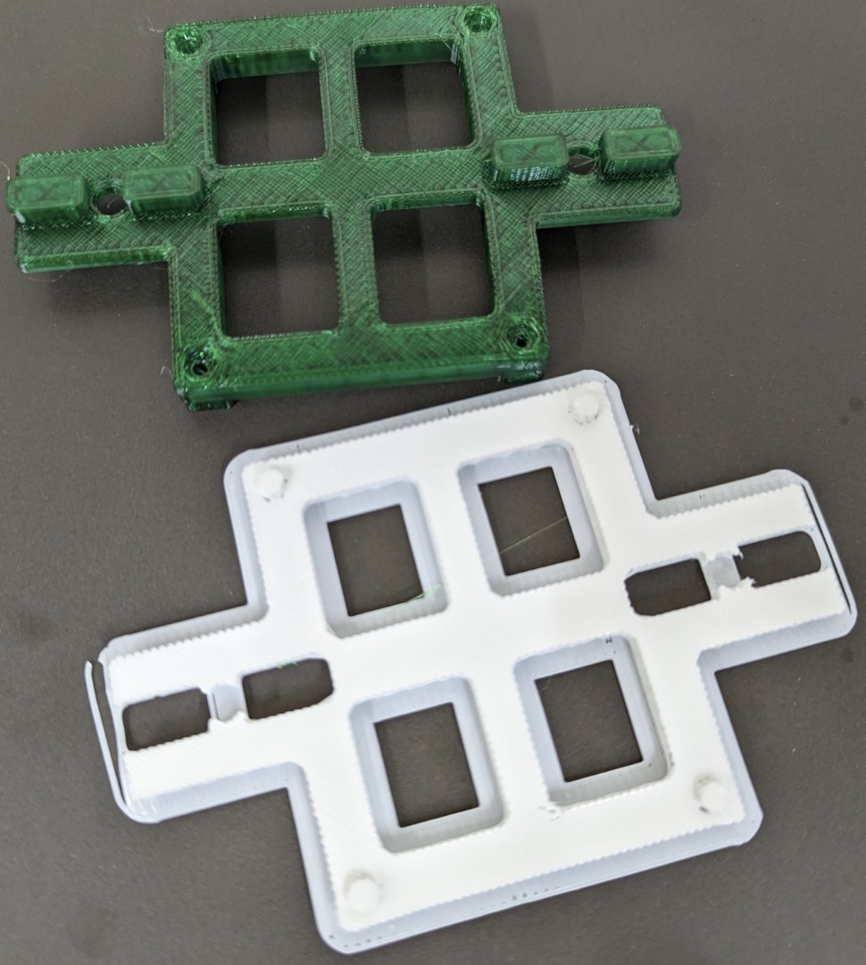
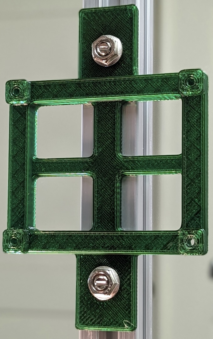
I’m quite happy with how this bracket turned out. The green is PETG and the white is PLA. This is the first orientation I printed.
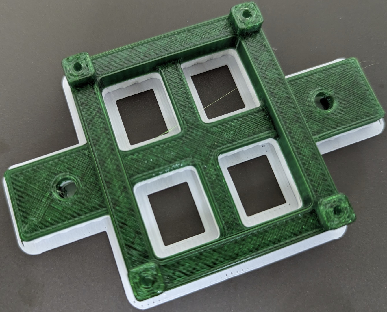
The support sometimes sticks at first but it peels off much more cleanly than if I used the same material for printing and supports. These large flat surfaces usually have a nice finish afterward but I did see some curling on one corner.
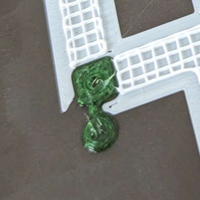
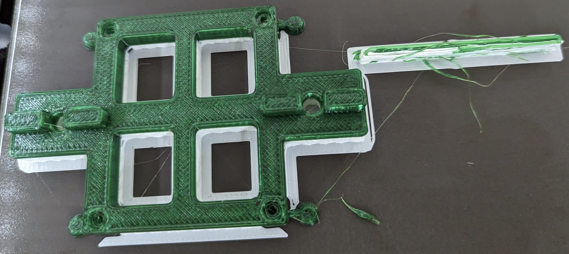
My last couple prints added the extra adhesion bits and I flipped the whole thing over. The small surfaces can be seen here after a few layers are printed. The green PETG would come off the print bed more easily without the extra little disc to hold it in place. After the print is complete it’s easy to cut these little things off.
The wipe tower is really stringy even though I’m drying the PETG filament before printing. It is super old filament though so I’m not going to blame the Prusa XL until I’ve tried a couple more tweaks.
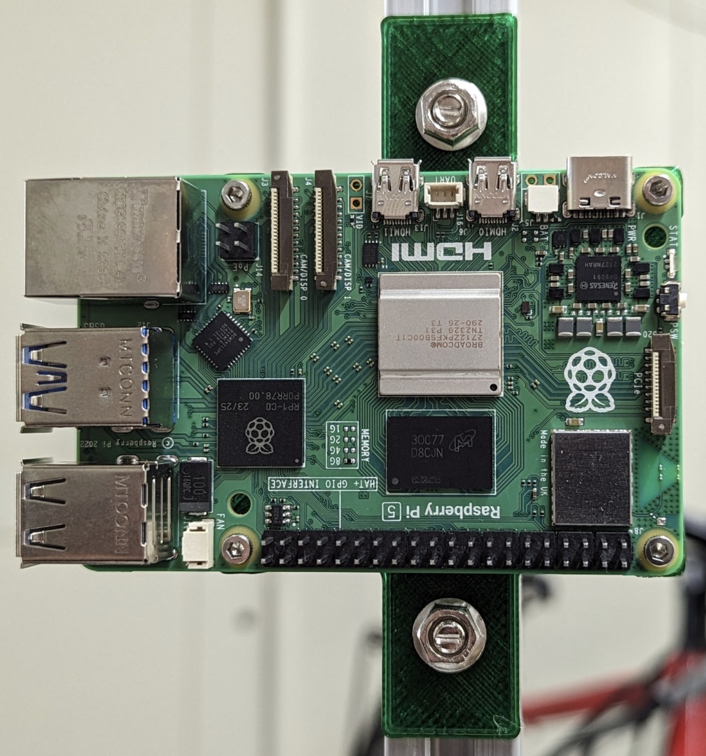
The bracket is pretty easy to install. I used 12mm machine screws and nuts (M2.5, 4 of each) to secure the PCB to the bracket. To attach the bracket I used two M5 hammerhead bolts with the corresponding nuts. I could have used 8mm M5 bolts with T-nuts instead.
And finally here it is with the PCB mounted. It fits either the Raspberry Pi 4B or the 5.
Ultimately this bracket will be part of the next Gamma Camera build. It’s not the exactly the replacement compute cage I envisioned but I like the simplicity of this bracket and simplicity is an important design goal.